Reverse Engineering (RE) is the process of discovering the technological principles of a device, object or system through analysis of its structure, function and operation. In this method, what is often done is to produce a new software or tool that will perform the same task, without copying the original, and it often involves taking apart the parts of something (e.g., a mechanical device, electronic component, or software program) and analyzing its working principles in detail.
As computer-aided design (CAD) has become more popular, reverse engineering has become a viable method to create a 3D virtual model of an existing physical part for use in 3D computer-aided design (CAD), computer-aided manufacturing (CAM), computer-aided engineering (CAE) or other software.
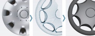
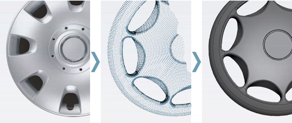
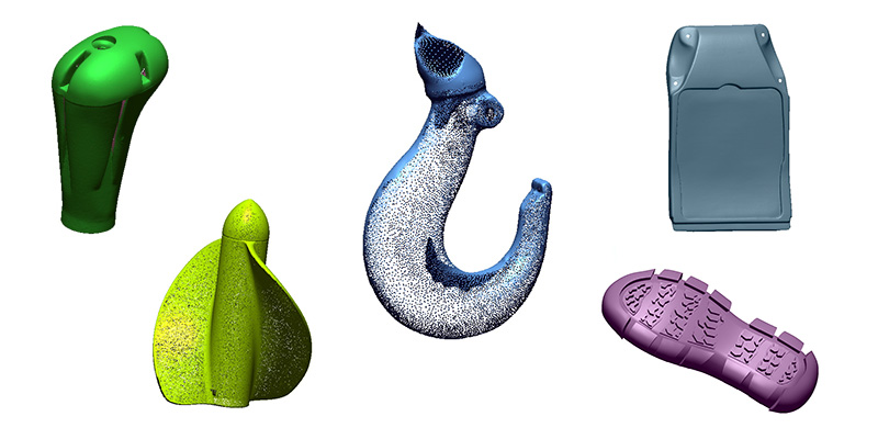
The reverse-engineering process involves measuring an object and then reconstructing it as a 3D model. The physical object can be measured using 3D scanning technologies like coordinate measuring machines (CMM), laser scanners, structured light digitizers or computed tomography. The measured data alone, usually represented as a point cloud, lacks topological information and is therefore often processed and modeled into a more usable format such as a triangular-faced mesh, a set of NURBS surfaces or a CAD model. Point clouds are not compatible with many 3D software therefore Reverse Engineering software can convert the point clouds into formats that can be used in visualizations or in software like 3D CAD, CAM, CAE.
Reverse Engineering Service
It’s hard and not accurate to draw parts in digital platforms by using the traditional ways of measuring them in real life in order to get digital data to be used on computer if you have a part that needs to be changed, developed or manufactured. In Reverse Engineering you can obtain the data of these parts in STL or point cloud formats in a shorter time with the help of 3D laser or optical scanning systems. CAD models of the scanned-measured parts are created through the help of the NURBS splines which are accurately obtained from these data.
Purpose of the Reverse Engineering Process
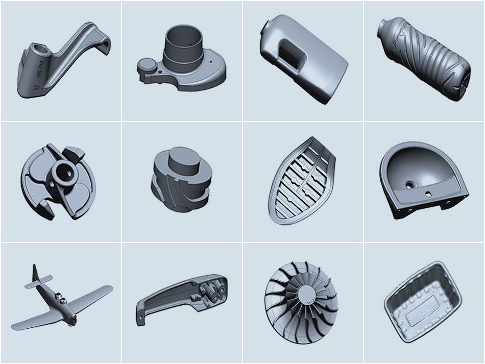
Reverse Engineering method is often used for creating 3D surfaces or solid models by using STL data.
+ Processes which take days or weeks to duplicate a part with traditional ways can be accomplished in hours just by duplicating the product through scanning and rapid processing.
+ It is possible to obtain a new model after adjusting the CAD data of a part with created by using the reverse engineering method when you want to create a part by modifying the existing physical part itself.
+ Reverse Engineering is also used to transfer a handmade object to digital platform and create CAD data.
+ Reverse Engineering method is also used to reform and process the deformed-ruined tools, molds, dies and parts.
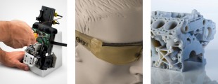
3D Scanning Services (Digitization – Laser/Optic)
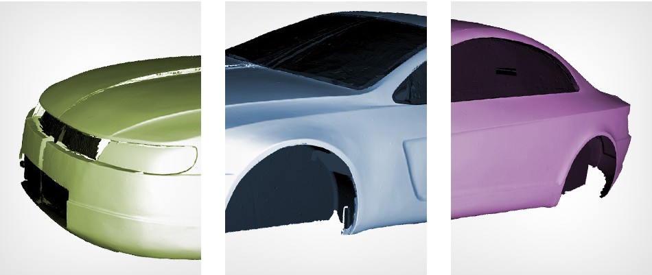
Any 3D physical object, part or system (e.g. mould, fixture, product, assembled systems, metal, plastic, formed surfaces) can be scanned by our 3D scanning devices and their digital data can be acquired as point clouds. These point cloud data are converted into polygon mesh structure (triangle polygon data) via 3D Scanning Systems in order to obtain surface data as .stl formats.
Thus targeted part or system is transferred to digital platform as point clouds/.stl data. Now you have a 3D data that can be modified in any way you want.
3D Scanning Options: Laser or Optical Systems
Scanning process can be done by “Laser” or “Optical” systems. It can be accomplished in a couple hours by our 3D Scanning Systems while it would take weeks to do it with traditional ways such as marking points on the part.
Basically detailed part structure and/or roughness of the part’s surface will affect the scan process’s result and scan time. All the details cannot be digitized when roughness and complexity of the parts increase therefore it will take more time for a high quality result.
Surfaces that are going to be scanned should be painted as matt white powder coat in highlighted environments or if the part is bright or transparent. In this way you will obtain more detailed high quality scan data.
Applications you can do with the .stl data you’ve got from 3D Scanning:
+ Reverse Engineering
+ Rapid Prototyping
+ Direct tool path generation on scan data by supported CAM software for CNC milling
+ Part Measurement
+ Quality Control
+ Process Control
If we explain them in details:
+ These data can be used in the process of obtaining CAD data of the parts that don’t have CAD data in digital platform (Reverse Engineering).
+ These data can be used to duplicate a sample part by rapid prototyping.
+ Point clouds that are obtained can be used as surface data in the format of STL(polygon mesh). Some CAM softwares are directly able to generate tool path on polygon mesh so that data can directly use for manufacturing when result is good enough.
+ It can transform the work of conventional CMMs into mobile system thus saving from time and cost of extra staff. In this way mould/die, fixture, product and assembled systems can be measured.
+ It can be used in the comparison of the manufactured product with the 3D CAD model.
+ It can be used to determine the deformation and corrosions that can happen in the moulds/dies which are used for a long time.
+ It can be used to evaluate the spring-back of the sheet metal tools.
For more detailed information: reservice@avrotas.com